Shock Absorbing Regenerative Backpack
Project Description
The Shock Absorbing Regenerative Backpack was a group project as part of the DESN2000 - Engineering Design and Professional Practice course at UNSW.
Our group was tasked with creating a device that satisfied the following:
- The energy accumulation module functions to derive energy from an external source outside the energy harvesting device.
- The energy storage module functions to store the accumulated energy inside the energy harvesting device.
- The energy utilization module utilizes the harvested energy to power other some meaningful device.
Our group decided to make a backpack that is able to harvest the vertical motion of human gait to generate electricity to charge a portable charger. A byproduct of achieving this objective was creating an active shock dampener that reduced perceived load on the shoulders.
Technologies Used
Roles and Contributions
- Team Leader.
- Researching solutions with respect to design priciples.
- Sketching desired product.
- CAD model for 3D printed prototype.
- Circuit Design.
- Testing Prototype.
- CAD model for final item in Solidworks.
Process
I was selected as team leader for this particular case as I had the most experience working with circuitry, fabricating and prototyping. The other four members of my group were second year mechanical engineers whereas I was a fourth year mechatronics engineer who understood energy generation principles.
I quickly mocked up a concept sketch for how the product should look like.

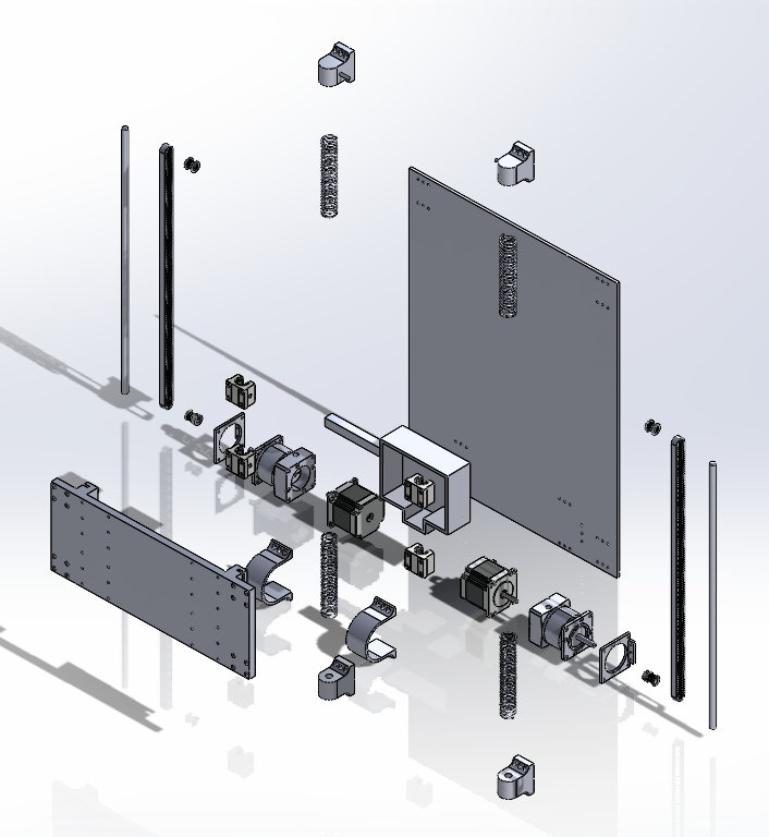
The next step was to make the idealised version of the product in SOLIDWORKS as this was the application our team was most familiar with.

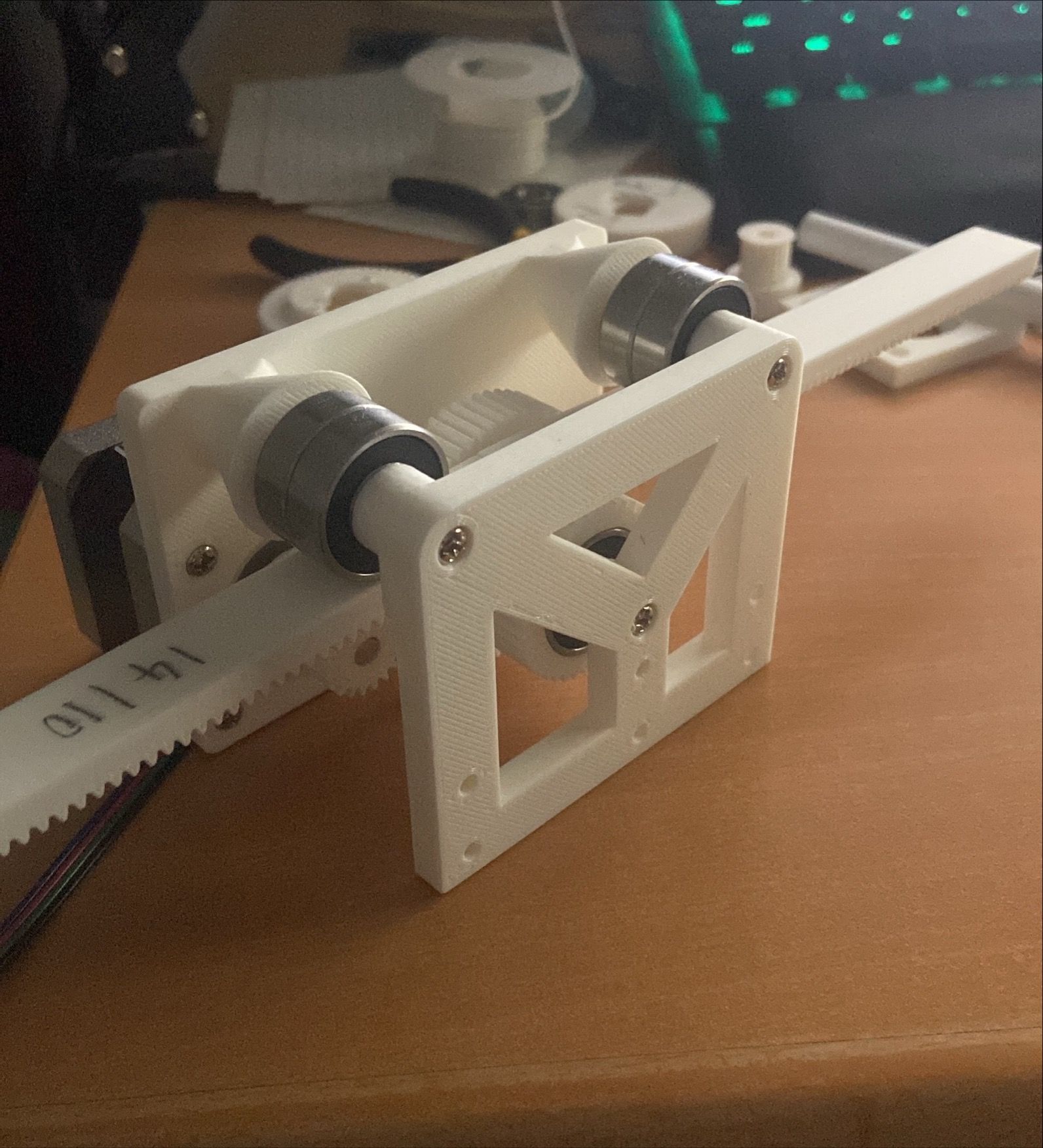
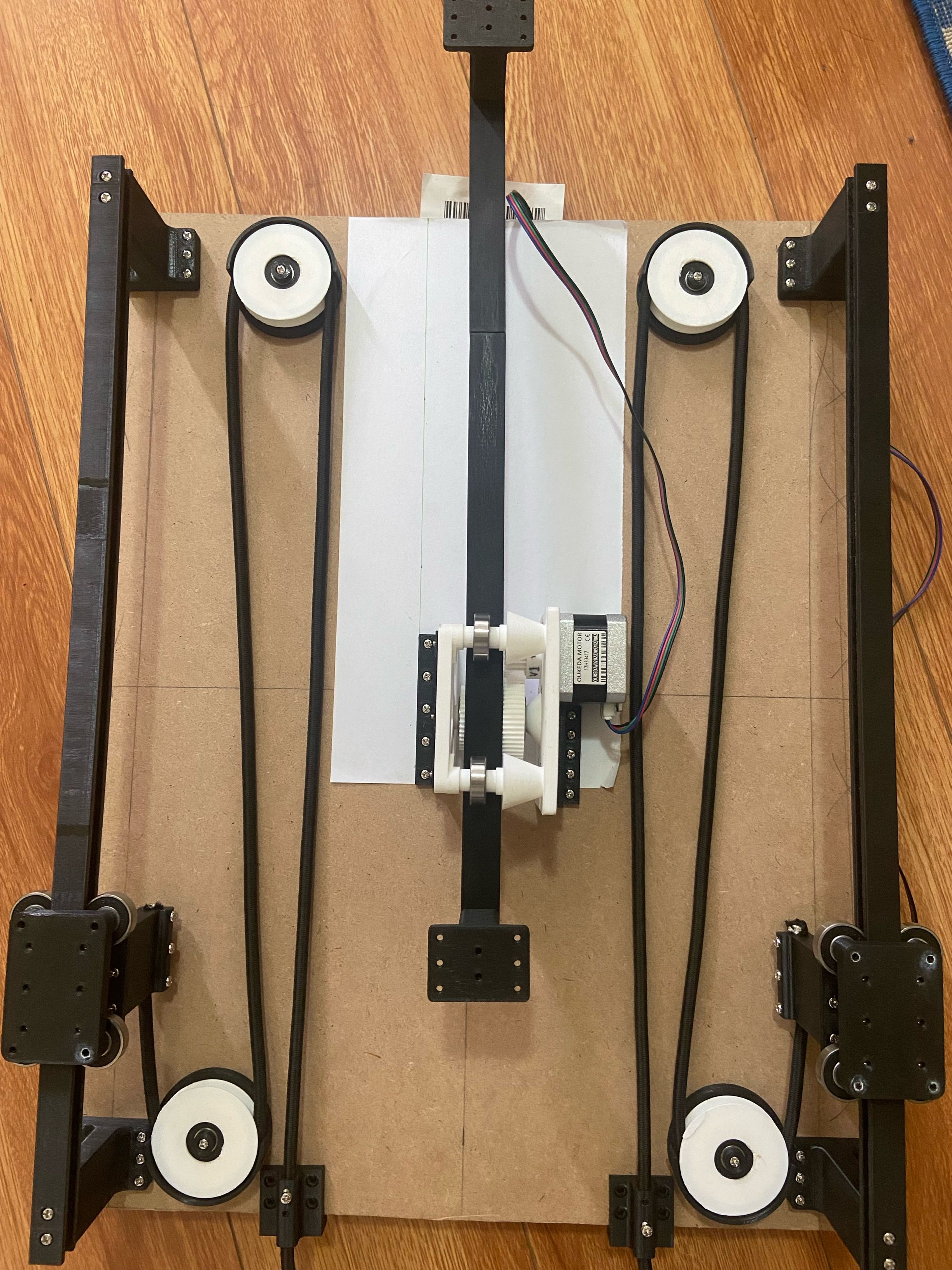
I then fabricated each part of for the prototype using Fusion360 and 3D printing. Bungee cords were used to create the suspension system.
The main ideas for the electrical circuitry was inspired by this helpful video from Robert Murray-Smith.
Since I will be generating power with electric motors, the output will be sinusoidal in nature. As such I will need to rectify, smooth and finally regulate its voltage output to 5v DC.

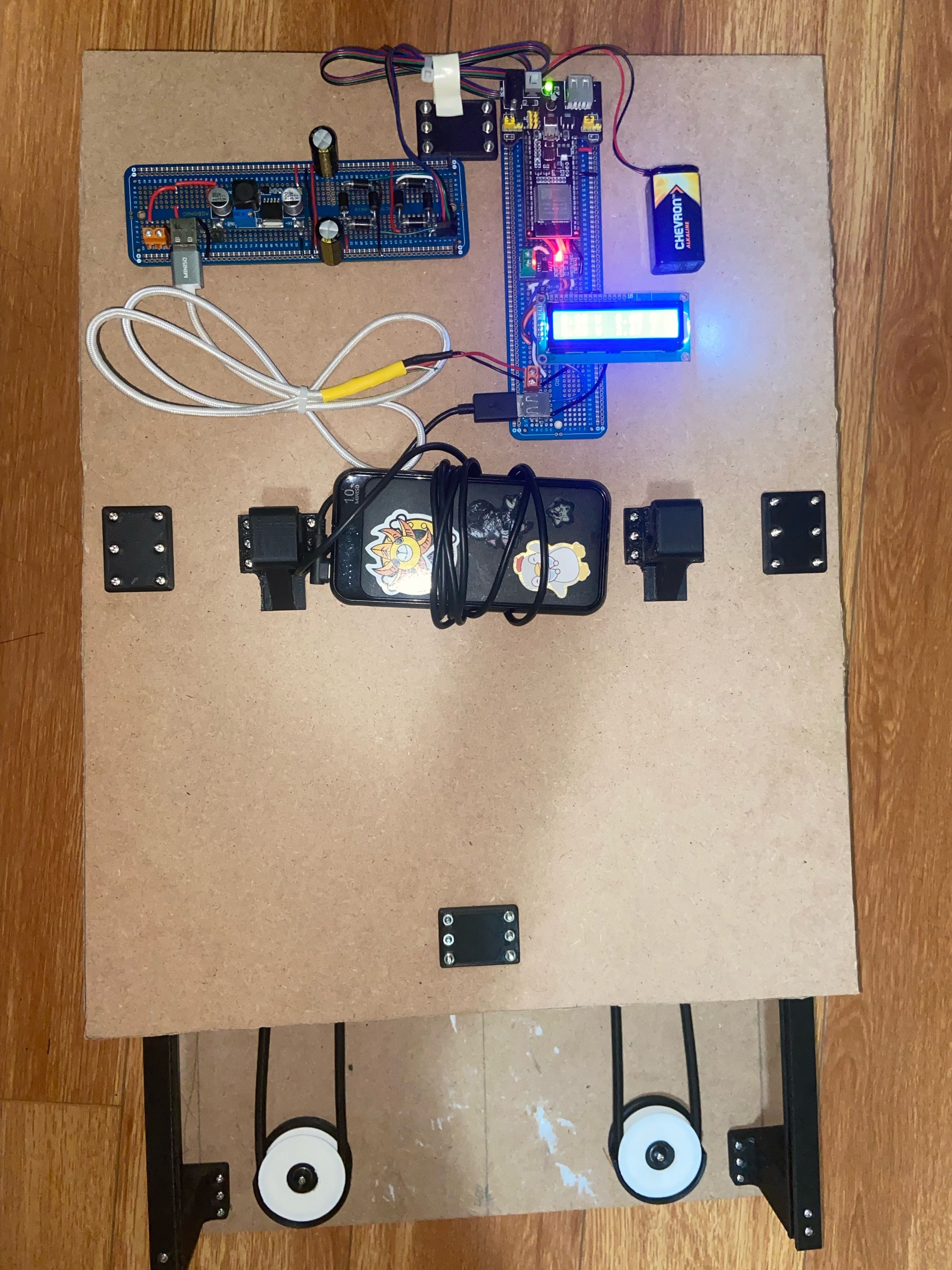
After soldering, the circuitry looks like this:

After assembly, the final product looks like this:
Results
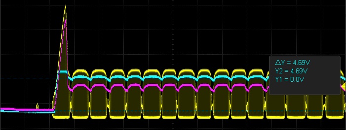
As shown on the oscilloscope output (cyan line), the final output oscillates about 4.69 volts.
