Breadboard GPU
Project Description
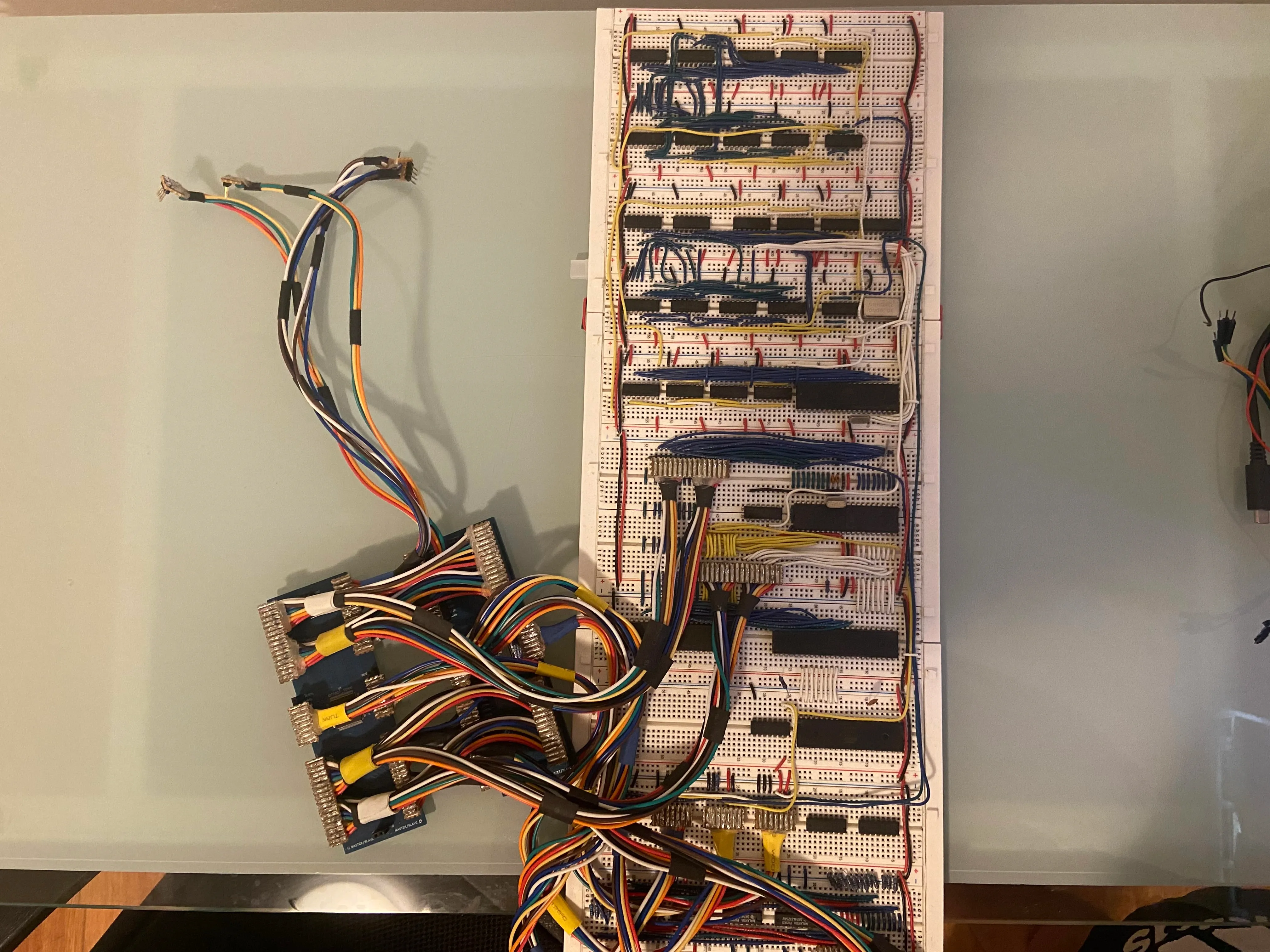
This was a project that I decided to do on a whim during my summer break over 2021 after complete a digital circuits course in university. It is a breadboard computer that was build following the guidance of youtuber Ben Eater and his homemade graphics card series.
It was a great way for learning the subtle intricacies of electronics engineering and also learning how to interpret datasheets.
In case you would like to check out his series below,
This project involved extensive use of breadboards, digital circuits, and datasheets for different components.
The main technologies used in this project included TTL ICs, diodes, capacitors, resistors, and most importantly, a VGA connector for output. I also utilized C++ for generating writing my own naïve graphics API and other necessary digital logic.
Technologies Used
Features
The graphics card I decided to build was slightly different to the one from Ben Eater mainly because I wanted to challenge myself and test my overall understanding of the content.
Namely the key differences will be:
| Feature | Ben Eater | Mine |
|---|---|---|
| Resolution | 100:75 | 200:150 |
| VRam Type | EEPROM (AT28C256) | SRAM (AS6C1008-55PCN) |
| Framebuffer | Single buffered | Double buffered |
| Colour Range | 64 colours | 4096 colours |
| CPU Type | W65C02S 8–bit Microprocessor | ATMEGA1284-PU Microcontroller |
| CPU Access | During blanking intervals | No restrictions |
| Breadboard Type | Solderless | Soldered |
Timing Circuitry
By following Ben Eater’s guide, I was quickly able to build the breadboard setup for displaying simple RGB bands on the monitor.
VRAM Circuitry
A huge limitation in Ben Eater's design was that the EEPROM only had 15 address lines and hence, the maximum supported resolution was 100 x 75. In addition, his graphics card can only render 64 different colours. Because I wanted to render games on my GPU, I opted to use the AS6C1008-55PCN- 1Mbit instead of an EEPROM with for a final resolution of 200 x 150 and 4096 supported colours.
Driver
The main computing unit for this graphics card was ATMEGA1284-PU microcontroller the reason for this was due to it having 32 GPIO pins in which I would need 16 for the address, 12 for I/O and 1 to control which SRAM is in read/write mode.
Initially the main bottleneck was the digital write function being too slow for my needs since they only operated on one pin at a time and performed checks on the input. As such, I will be writing my own C function to accomplish the task with zero overhead using port manipulation. This allowed me to dramatically improve the time to write from 2.24us for a single bit to 23ns for 8 bits in parallel.
In case you wanted to know, this is what the code was:
void writeToBuffer(uint16_t addr, uint16_t word) {
    PORTB = addr >> 8; // Higher Addr Bytes
    PORTA = addr & 0xFF; // Lower Addr Bytes
    PORTC = (word >> 8) & 0b00111111;
    PORTD = word & 0xFF;
}
Note that I am setting the upper bytes first to avoid corrupting addresses in the SRAM.
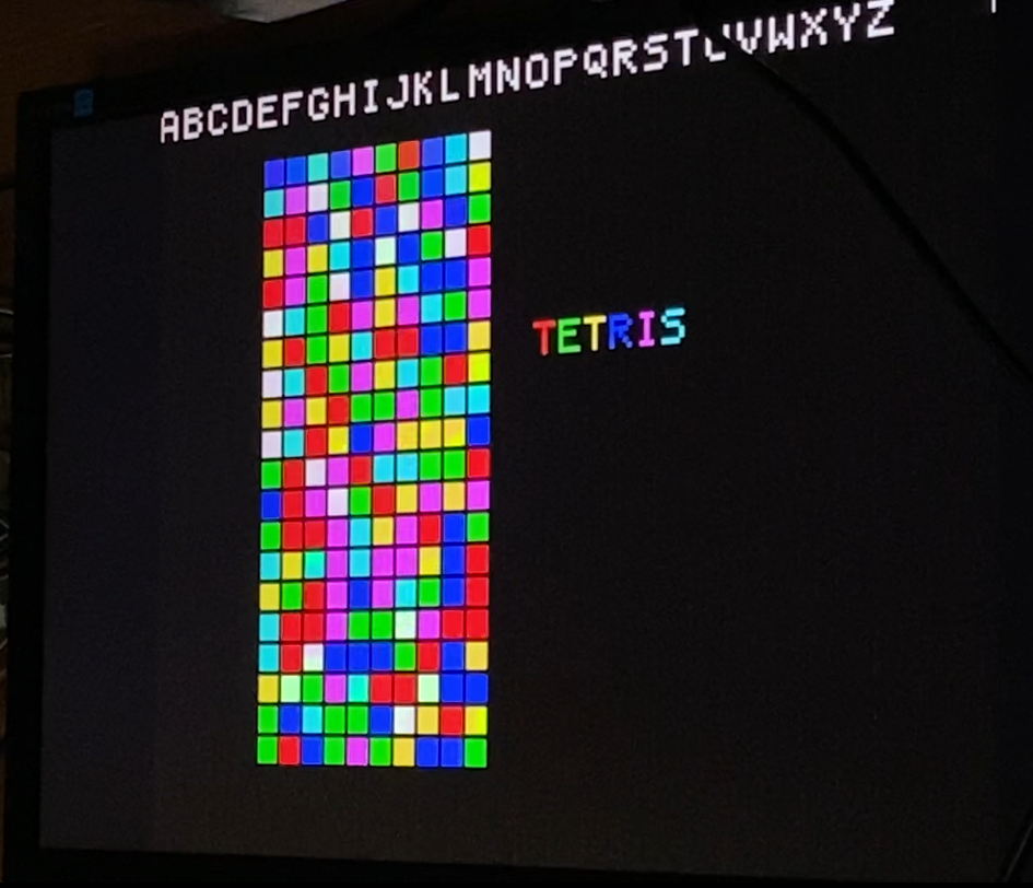
Since I was really into Tetris at the time, I thought it would be a cool idea to implement that as a playable game.
Results
Although, due to time and financial constraints, I had to halt development on the project. However, I plan to resume it someday, possibly after graduating from university when I might have a few more electrical circuit design tricks up my sleeve to streamline the process. Alternatively, I may choose to redo the project using proper PCBs instead of breadboards. Despite the abrupt halt, I was quite pleased with the progress I made in just a few weeks, especially considering I was a beginner in electronics engineering.
